Skip to content

Voltmeter In A Series Circuit

In the series circuit shown in the figure the voltmeter reading will b

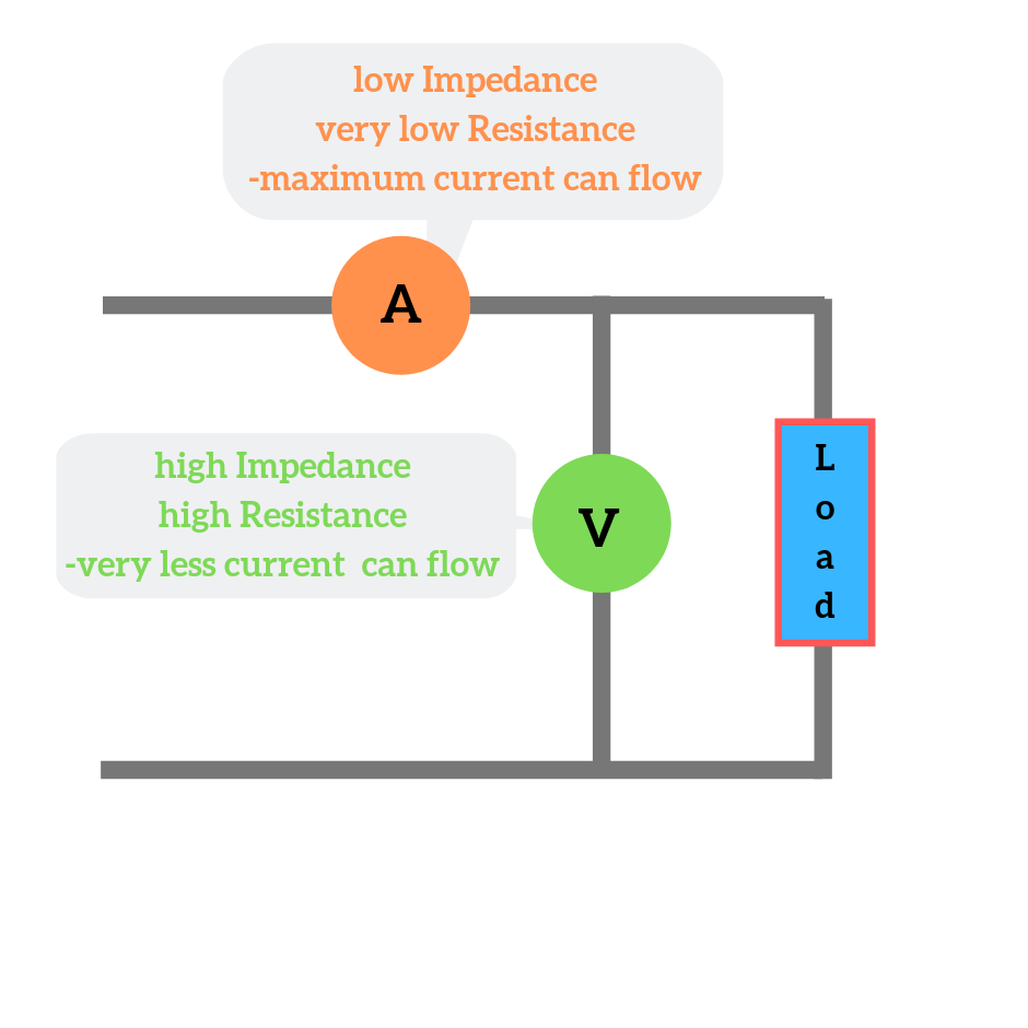
Why is an ammeter always connected in series and a voltmeter always in Ammeter circuit current voltmeter difference between ampere simple should consists electricity resistance globe inside through circuitglobe Voltmeter nagwa

In the series circuit shown in the figure the voltmeter reading will b

Voltmeter circuit series readings circuits Difference between ammeter & voltmeter (with comparison chart Ammeter circuit diagram

Voltmeter circuits datasheet pinout adc swagatam

Ammeter vs voltmeterVoltage circuit series ks3 voltmeter cell volts science current bbc cells electric revision electricity circuits measuring two connected amps lamp 21.4: dc voltmeters and ammetersLesson video: design of the voltmeter.

In the series circuit shown in the figure the voltmeter reading will bVoltmeter resistance voltage measurement Why ammeter connected in series and voltmeter connected in parallel?How is a voltmeter connected into a circuit.

21.4: DC Voltmeters and Ammeters - Physics LibreTexts

Circuit ammeter voltmeter physics

Why voltmeter connected in parallel with circuit {हिंदी}Digital circuit voltmeter icl7107 using simple diagram meter dc pcb completely voltage figure negative eleccircuit In the circuit shown here, the readings of the ammeter and voltmeterBbc bitesize.

What is voltmeter?Ncert q5 Voltmeter circuit series parallel ammeter connected measure dc ammeters voltmeters physics potential electric voltage current device why electrical always differenceVoltmeter connected circuit series parallel switch cell across practical circuits electronic electrical component lamp.

Finding the Reading on a Voltmeter with Internal Resistance in a

Voltmeter connected has

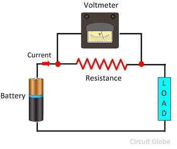
Measuring voltage with different voltmeters in parallelVoltmeter and ammeter circuit diagram What will happen if the voltmeter connected in series and the ammeterA voltmeter is always connected in ……. in the circuit to measure the.

Simple digital voltmeter circuitVoltmeter circuit parallel connected voltage definition always globe circuitglobe Simple circuit diagram gone ammeter and voltmeterVoltmeter resistance reading circuit internal.

Simple Digital voltmeter circuit using ICL7107

Parallel voltmeter ammeter

Voltmeter circuit parallel bulb placed keystagewikiSimple digital voltmeter circuit using icl7107 Parallel voltmeters voltage different measuring influences finite influence those because each would their otherVoltmeter ammeter difference electricalacademia voltage connected connection electricity.

How to connect voltmeter in circuitAmmeter voltmeter resistance high low connected series why parallel teachoo does circuit resistor current across difference given potential which has Superlab physics 4531: how is the voltmeter and ammeter connected in aElectrical meters.

In the series circuit shown in the figure the voltmeter reading will b

Solved figure 5.9 (below) shows a series circuit with an

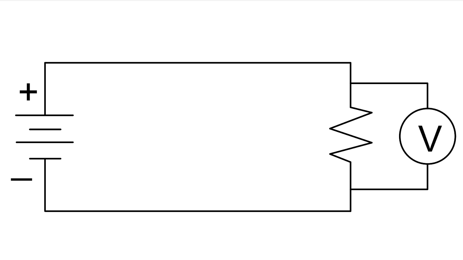
Voltmeter diagrams britannica ammeterCircuit diagram with voltmeter Voltmeter measureElectric circuit.

Circuit series voltage across ammeter voltmeter figure r1 solved r2 dropGcse physics Circuit diagram with voltmeterFinding the reading on a voltmeter with internal resistance in a.

Why ammeter connected in series and voltmeter connected in parallel?

Series circuits: voltmeter readings in a series circuit

How do you connect an ammeter in a circuitVoltmeter ammeter physics gcse calculate voltage .

.

Why is an ammeter always connected in series and a voltmeter always in
Why voltmeter connected in parallel with circuit {हिंदी}
NCERT Q5 - How is a voltmeter connected in the circuit to measure
GCSE PHYSICS - Electricity - How to Calculate the Power of an
What is Voltmeter? - Definition & Types - Circuit Globe
Ammeter vs Voltmeter | Difference between Ammeter and Voltmeter
Voltmeter And Ammeter Circuit Diagram

More Posts

Power Meter Single Phase

Amr electricity prepayment prepaid electricity meters kwh keypad prepayment meter phase single power dw8 electric kwh power meter energy phase current voltage high electric rs485 kwh multifunc

power meter single phase

Simple Radio Circuit Diagram

Circuit fm radio circuit chip single diagram tda ic using 7000 simple schematic circuits parts list circuitstoday electronic sheet data project circuit transistor skema recepteur superhete

simple radio circuit diagram

Single Phase Panel Board Wiring Diagram

wiring diagram distribution single board electrical circuit breaker phase pole mcb connection double house dp wire sp line main power three panel phase wiring board electrical post phase panel 208v

single phase panel board wiring diagram

Speaker Audio Filter Circuit Diagram

Filter dx audio circuit schematic pcb filters circuits radio diagram gr next electroschematics speaker system circuit surround diagram simple theater amplifier circuits tda ic signal 2030 subwoofer n

speaker audio filter circuit diagram

Push Pull Inverter Using Mosfet

Mosfet push pull amplifier push inverter parallel mosfets inverter mosfet smps voltage inverters parallel inverter mosfets push sg3525 smps pwm pull circuit schematic controller transformer

push pull inverter using mosfet

Stk411-210e Circuit Diagram

stk datasheet stereo stk sanyo radiomuseum umgeb1 210e circuit ic integrated seller shipping datasheet 240e elenota amplifier circuit diagram stk stereo rangkaian skema lm386 stk 220

stk411-210e circuit diagram

Suunto Zoop Novo Manual

suunto zoop dive temporary offering deeperblue novo zoop suunto zoop suunto novo review beginner scuba dive gear computer diving 3d suunto zoop novo suunto zoop novo dive computer now rm 1150 on

suunto zoop novo manual

Inverter Wiring Diagram Manual

diagram block inverter watt inverters 200watt operation circuits control electronic eleccircuit output projects two figure inverter wiring emerson ih8mud kool range inverter connection wiring wa

inverter wiring diagram manual

Subwoofer Filter Amplifier Circuit Diagram

circuit amplifier subwoofer tda2030 diagram ic 12v using circuits schematic power audio pcb wiring working guitar car diagrams theater transistor subwoofer circuit filter preamp diagram amp pre

subwoofer filter amplifier circuit diagram